What are PCB tolerances?
PCB tolerances refer to the acceptable range of variations in the dimensions, spacing, and other physical characteristics of a printed circuit board (PCB) during the manufacturing process. These tolerances are essential to ensure that the PCB functions as intended and meets the required specifications.
Types of PCB Tolerances
There are several types of PCB tolerances that need to be considered during the design and manufacturing process:
-
Dimensional Tolerances: These tolerances refer to the acceptable range of variations in the physical dimensions of the PCB, such as length, width, and thickness.
-
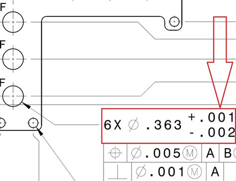
Hole Tolerances: These tolerances relate to the acceptable range of variations in the size and position of drilled holes on the PCB, including through-holes and vias.
-
Copper Thickness Tolerances: These tolerances refer to the acceptable range of variations in the thickness of the copper layers on the PCB.
-
Solder Mask Tolerances: These tolerances relate to the acceptable range of variations in the dimensions and registration of the solder mask on the PCB.
-
Silkscreen Tolerances: These tolerances refer to the acceptable range of variations in the dimensions and registration of the silkscreen markings on the PCB.
Why are PCB Tolerances Important?
PCB tolerances are crucial for several reasons:
-
Functionality: Adhering to the specified tolerances ensures that the PCB functions as intended. Deviations from the tolerances can lead to issues such as poor electrical connections, short circuits, or signal integrity problems.
-
Compatibility: PCB tolerances ensure that the board is compatible with the components that will be mounted on it. If the tolerances are not met, components may not fit properly or may not function as expected.
-
Reliability: Maintaining tight tolerances during the manufacturing process helps to improve the reliability of the PCB. Consistent and accurate dimensions, spacing, and other characteristics reduce the risk of failures and increase the longevity of the board.
-
Cost: Adhering to PCB tolerances helps to minimize waste and rework during the manufacturing process, which can lead to cost savings.

Factors Affecting PCB Tolerances
Several factors can affect the ability to maintain tight PCB tolerances during the manufacturing process:
-
Manufacturing Process: The chosen manufacturing process, such as etching, drilling, or plating, can impact the achievable tolerances. Some processes have inherent limitations in terms of precision and accuracy.
-
Material Properties: The properties of the PCB substrate material, such as its thermal expansion coefficient and dimensional stability, can affect the tolerances that can be achieved.
-
Equipment Capabilities: The capabilities of the manufacturing equipment, such as the accuracy of the drilling machines or the resolution of the imaging systems, can limit the achievable tolerances.
-
Design Complexity: The complexity of the PCB design, including the number of layers, the density of the traces, and the presence of fine-pitch components, can make it more challenging to maintain tight tolerances.

Specifying PCB Tolerances
When designing a PCB, it is essential to specify the required tolerances clearly. This information should be communicated to the PCB manufacturer to ensure that the board is produced to the desired specifications.
IPC Standards for PCB Tolerances
The IPC (Association Connecting Electronics Industries) has established standards for PCB tolerances. These standards provide guidelines for specifying and measuring tolerances in PCB manufacturing.
Some of the relevant IPC standards include:
- IPC-6012: Qualification and Performance Specification for Rigid Printed Boards
- IPC-6013: Qualification and Performance Specification for Flexible Printed Boards
- IPC-6018: Qualification and Performance Specification for High Frequency (Microwave) Printed Boards
These standards define various classes of PCBs based on their intended application and the required level of quality and reliability. Each class has specific requirements for tolerances.
Communicating Tolerances to PCB Manufacturers
When placing an order for PCBs, it is important to communicate the required tolerances clearly to the manufacturer. This can be done through fabrication drawings, specifications, or other documentation.
The fabrication drawing should include:
- Dimensional tolerances for the overall board size and any critical features
- Hole tolerances for drilled holes and vias
- Copper thickness tolerances for each layer
- Solder mask and silkscreen tolerances
- Any other relevant tolerances specific to the design
It is also important to discuss the tolerances with the PCB manufacturer to ensure that they are capable of meeting the requirements. Some manufacturers may have specific capabilities or limitations that need to be considered.

Measuring and Verifying PCB Tolerances
Once the PCBs have been manufactured, it is important to measure and verify that the tolerances have been met. This process is known as PCB Inspection.
PCB Inspection Methods
There are several methods for inspecting PCBs to verify that the tolerances have been met:
-
Visual Inspection: This involves visually examining the PCB for any obvious defects or deviations from the specified tolerances. This can be done with the naked eye or using magnification tools.
-
Automated Optical Inspection (AOI): AOI systems use cameras and image processing algorithms to automatically inspect the PCB for defects and measure critical dimensions. This method is faster and more consistent than manual visual inspection.
-
X-Ray Inspection: X-ray inspection systems can be used to inspect the internal structure of the PCB, including the alignment of drilled holes and the integrity of vias and other internal features.
-
Coordinate Measuring Machine (CMM): CMMs are precision measuring instruments that can be used to measure the physical dimensions of the PCB with high accuracy. This method is often used for critical dimensions or when very tight tolerances are required.
Dealing with Out-of-Tolerance PCBs
If the PCB inspection reveals that the tolerances have not been met, there are several options for dealing with the out-of-tolerance boards:
-
Rework: In some cases, it may be possible to rework the PCBs to bring them within the specified tolerances. This may involve drilling new holes, adding or removing copper, or making other modifications to the board.
-
Acceptance with Deviation: If the deviations from the tolerances are minor and do not affect the functionality or reliability of the board, it may be possible to accept the PCBs with a deviation. This should be done in consultation with the PCB designer and the end customer.
-
Rejection: If the deviations from the tolerances are significant and cannot be reworked or accepted with a deviation, the PCBs may need to be rejected and remanufactured.
FAQ
-
What are the most common PCB tolerances?
The most common PCB tolerances include dimensional tolerances, hole tolerances, copper thickness tolerances, solder mask tolerances, and silkscreen tolerances. -
What is the importance of PCB tolerances in PCB manufacturing?
PCB tolerances are important because they ensure that the PCB functions as intended, is compatible with the components that will be mounted on it, and is reliable over its intended lifespan. Adhering to tolerances also helps to minimize waste and rework during the manufacturing process. -
How are PCB tolerances specified?
PCB tolerances are typically specified through fabrication drawings, specifications, or other documentation provided to the PCB manufacturer. The tolerances should be clearly communicated and discussed with the manufacturer to ensure that they are capable of meeting the requirements. -
What are some methods for inspecting PCBs to verify that tolerances have been met?
Methods for inspecting PCBs include visual inspection, automated optical inspection (AOI), X-ray inspection, and coordinate measuring machines (CMMs). These methods can be used to measure critical dimensions and check for defects or deviations from the specified tolerances. -
What happens if a PCB is found to be out of tolerance?
If a PCB is found to be out of tolerance, there are several options depending on the severity of the deviation. Minor deviations may be acceptable with a deviation, while more significant deviations may require rework or rejection of the PCBs. The appropriate course of action should be determined in consultation with the PCB designer and the end customer.
Conclusion
Manufacturing tolerances are a critical aspect of PCB design and manufacturing. Adhering to the specified tolerances ensures that the PCB functions as intended, is compatible with the components that will be mounted on it, and is reliable over its intended lifespan.
When designing a PCB, it is important to specify the required tolerances clearly and communicate them to the PCB manufacturer. IPC standards provide guidelines for specifying and measuring tolerances in PCB manufacturing.
Once the PCBs have been manufactured, they should be inspected to verify that the tolerances have been met. Various inspection methods can be used, including visual inspection, AOI, X-ray inspection, and CMMs.
If a PCB is found to be out of tolerance, the appropriate course of action should be determined based on the severity of the deviation. This may involve rework, acceptance with a deviation, or rejection of the PCBs.
By understanding and properly specifying PCB tolerances, designers and manufacturers can work together to produce high-quality, reliable PCBs that meet the required specifications.


Leave a Reply