Introduction to PCB Legends
In the world of printed circuit boards (PCBs), the legend is an essential component that helps users identify and understand the various elements on the board. A PCB legend, also known as silkscreen or overlay, is the text and symbols printed on the surface of a PCB that provide information about the board’s components, connectors, and other features. This article will delve into the details of PCB legends, their importance, and how they are created.
What is a PCB Legend?
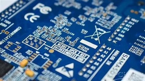
A PCB legend is a layer of text and symbols printed on the surface of a printed circuit board. The legend is typically white in color and is applied using a silkscreen printing process. The purpose of the legend is to provide a clear and concise way to identify the various components, connectors, and other features on the PCB.
The legend includes information such as:
- Component reference designators (e.g., R1, C2, U3)
- Component values (e.g., 10K, 100nF, 74HC00)
- Polarity indicators for capacitors and diodes
- Pin numbers for integrated circuits and connectors
- Test points and other special features
- Company logos and product information
The Importance of PCB Legends
PCB legends play a crucial role in the manufacturing, assembly, and maintenance of electronic devices. Some of the key benefits of having a well-designed PCB legend include:
-
Ease of Assembly: A clear and accurate PCB legend makes it easier for assembly technicians to locate and place components on the board correctly. This reduces the likelihood of errors and improves the overall quality of the assembled product.
-
Simplified Troubleshooting: When a device malfunctions, a technician can use the PCB legend to quickly identify components and test points, making it easier to diagnose and fix the problem.
-
Enhanced Communication: PCB legends serve as a common language between designers, manufacturers, and end-users. They ensure that everyone involved in the product lifecycle has a clear understanding of the board’s layout and functionality.
-
Improved Documentation: The information provided by the PCB legend can be used to create accurate schematics, bill of materials (BOM), and other documentation essential for the product’s lifecycle management.
-
Professional Appearance: A well-designed PCB legend gives the product a professional and polished look, which can be important for consumer-facing products or when showcasing the device to potential clients or investors.
Designing PCB Legends
Creating an effective PCB legend requires careful planning and attention to detail. Some key factors to consider when designing a PCB legend include:
1. Legend Placement
The placement of the legend on the PCB is crucial for readability and clarity. Some guidelines for legend placement include:
- Avoid placing legend text or symbols over component pads or traces
- Maintain a clear space around components to allow for easy identification
- Place the legend on the same side of the PCB as the components they refer to
- Consider the orientation of the board during assembly and use when placing the legend
2. Font and Symbol Selection
The choice of font and symbols used in the PCB legend can impact its readability and overall appearance. Some tips for font and symbol selection include:
- Use a clean, simple font that is easy to read at small sizes (e.g., Arial, Helvetica)
- Ensure that the font size is large enough to be easily read, typically at least 0.8mm in height
- Use standard symbols and abbreviations wherever possible (e.g., “+” for positive polarity, “TP” for test points)
- Avoid using overly decorative or complex fonts or symbols that may be difficult to read or interpret
3. Color and Contrast
The color and contrast of the PCB legend are important for visibility and legibility. In most cases, a white legend on a dark background (e.g., green, blue, black) provides the best contrast and readability. However, in some situations, such as with white solder mask PCBs, a black legend may be used instead.
It is also important to ensure that the legend color is compatible with the solder mask and will not fade or discolor over time due to exposure to heat or chemicals.
4. Legend Accuracy
Ensuring the accuracy of the PCB legend is critical for avoiding assembly errors and simplifying troubleshooting. Some tips for maintaining legend accuracy include:
- Double-check the legend against the schematic and BOM to ensure that all components and references are correctly labeled
- Use automated tools or scripts to generate the legend data from the CAD files to minimize the risk of manual errors
- Perform a final review of the legend before sending the PCB design for manufacturing

PCB Legend Creation Process
The process of creating a PCB legend typically involves the following steps:
-
Design: The PCB designer creates the legend data as part of the overall PCB design process. This includes placing component reference designators, values, and other information on the silkscreen layer of the CAD file.
-
Gerber File Generation: Once the PCB design is complete, the designer generates Gerber files, which are the industry-standard format for describing PCB layouts. The silkscreen layer is included as a separate Gerber file.
-
Film Preparation: The PCB manufacturer uses the silkscreen Gerber file to create a film that will be used to transfer the legend onto the PCB surface. This film is typically a clear plastic sheet with the legend data printed in black ink.
-
Screen Preparation: A fine mesh screen is coated with a light-sensitive emulsion and exposed to UV light through the legend film. The areas of the emulsion exposed to light harden, while the unexposed areas remain soluble.
-
Screen Washing: The screen is washed with water, which dissolves the unexposed emulsion, leaving behind a stencil of the legend data.
-
Ink Application: The screen is placed over the PCB, and a rubber squeegee is used to force the legend ink through the stencil onto the PCB surface.
-
Curing: The printed PCB is then heated in an oven to cure the legend ink and ensure its durability and adhesion to the board surface.

Advanced PCB Legend Techniques
In addition to the standard silkscreen legend, there are several advanced techniques that can be used to enhance the appearance and functionality of PCB legends:
1. Double-Sided Legends
For complex PCBs with components on both sides of the board, double-sided legends can be used to provide clear labeling for all components. This involves printing legends on both the top and bottom surfaces of the PCB, with each legend referring to the components on its respective side.
2. Multi-Color Legends
While most PCB legends are typically printed in a single color (white or black), some advanced applications may require multi-color legends for improved clarity or visual appeal. This can be achieved using multiple silkscreen passes with different color inks or by using specialized inkjet printing techniques.
3. Embedded Legends
Embedded legends are an alternative to traditional silkscreen legends, where the legend data is embedded directly into the PCB substrate. This can be achieved using techniques such as direct legend printing (DLP) or laser etching. Embedded legends offer several advantages, including improved durability, higher resolution, and the ability to create legends on non-flat surfaces.
4. Interactive Legends
With the increasing complexity of modern electronic devices, some PCBs are incorporating interactive legends that can provide additional information or functionality to users. This can include features such as:
- QR codes that link to online documentation or support resources
- NFC tags that can be scanned with a smartphone to access device settings or firmware updates
- Touch-sensitive buttons or sliders that can be used to control device functions or settings

FAQ
-
What is the purpose of a PCB legend?
A: The purpose of a PCB legend is to provide clear and concise information about the components, connectors, and other features on a printed circuit board. This information helps with assembly, troubleshooting, and documentation. -
What information is typically included in a PCB legend?
A: A PCB legend typically includes component reference designators, values, polarity indicators, pin numbers, test points, and other special features. It may also include company logos and product information. -
How is a PCB legend created?
A: A PCB legend is typically created using a silkscreen printing process. The legend data is generated as part of the PCB design process and used to create a film and stencil for printing the legend onto the PCB surface. -
Can PCB legends be printed in multiple colors?
A: Yes, while most PCB legends are printed in a single color (white or black), some advanced applications may require multi-color legends for improved clarity or visual appeal. This can be achieved using multiple silkscreen passes with different color inks or specialized inkjet printing techniques. -
What are embedded legends, and what advantages do they offer?
A: Embedded legends are an alternative to traditional silkscreen legends, where the legend data is embedded directly into the PCB substrate using techniques such as direct legend printing (DLP) or laser etching. Embedded legends offer improved durability, higher resolution, and the ability to create legends on non-flat surfaces.
Conclusion
PCB legends are a critical component of printed circuit board design, providing essential information for assembly, troubleshooting, and documentation. By understanding the importance of PCB legends and following best practices for their design and creation, PCB designers and manufacturers can ensure that their products are easy to assemble, maintain, and understand.
As PCB technology continues to evolve, we can expect to see new and innovative techniques for creating legends that enhance the functionality and user experience of electronic devices. From multi-color and embedded legends to interactive features like QR codes and touch-sensitive buttons, the future of PCB legends is exciting and full of possibilities.
| PCB Legend Element | Description |
|---|---|
| Component Reference Designators | Unique identifiers for each component on the PCB (e.g., R1, C2, U3) |
| Component Values | The value or rating of each component (e.g., 10K, 100nF, 74HC00) |
| Polarity Indicators | Symbols indicating the polarity of capacitors, diodes, and other polarized components |
| Pin Numbers | The numbered pins for integrated circuits, connectors, and other multi-pin components |
| Test Points | Special points on the PCB used for testing and debugging |
| Company Logos and Product Information | Branding elements and product-specific information, such as model numbers or serial numbers |
By including these essential elements in a well-designed PCB legend, designers and manufacturers can create printed circuit boards that are easy to assemble, troubleshoot, and maintain, ultimately leading to higher-quality and more reliable electronic devices.


Leave a Reply