Introduction
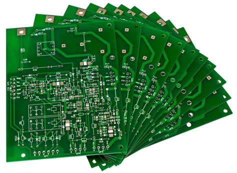
When it comes to manufacturing Printed Circuit Boards (PCBs), quality is paramount. PCBs are the backbone of modern electronics, and their reliability and performance directly impact the success of the end product. In this comprehensive article, we will explore the various aspects of PCB Quality assurance and how we, as a PCB manufacturer, can guarantee the quality of your PCBs.
Understanding PCB Quality
What is PCB Quality?
PCB quality refers to the overall reliability, functionality, and durability of a printed circuit board. A high-quality PCB should meet the following criteria:
- Proper functionality: The PCB should perform its intended functions without any issues.
- Reliability: The PCB should maintain its performance over its expected lifetime.
- Durability: The PCB should withstand the environmental conditions it is designed for.
- Manufacturability: The PCB design should be optimized for easy and efficient manufacturing.
Factors Affecting PCB Quality
Several factors can impact the quality of a PCB, including:
- Design: The PCB design must follow best practices and design rules to ensure manufacturability and reliability.
- Material selection: Using high-quality materials, such as copper, substrates, and solder masks, is crucial for PCB quality.
- Manufacturing processes: Adhering to strict manufacturing processes and quality control measures helps maintain PCB quality.
- Testing and inspection: Thorough testing and inspection at various stages of production ensure that quality issues are identified and addressed promptly.

PCB Design and Quality
Design for Manufacturability (DFM)
Design for Manufacturability (DFM) is an approach that optimizes the PCB design to improve manufacturability and reduce the likelihood of defects. Key aspects of DFM include:
- Following design rules: Adhering to the manufacturer’s design rules ensures that the PCB can be manufactured efficiently and with minimal issues.
- Optimizing component placement: Proper component placement improves manufacturability and reduces the risk of defects.
- Choosing appropriate trace widths and spacing: Selecting suitable trace widths and spacing based on the current requirements and manufacturing capabilities minimizes potential issues.
Design for Reliability (DFR)
Design for Reliability (DFR) focuses on creating PCB designs that are reliable and can withstand the intended operating conditions. Important factors in DFR include:
- Thermal management: Designing the PCB to efficiently dissipate heat and prevent thermal stress on components.
- Signal integrity: Ensuring that the PCB design minimizes signal integrity issues, such as crosstalk and electromagnetic interference (EMI).
- Mechanical stability: Designing the PCB to withstand mechanical stress and vibrations.

Material Selection and PCB Quality
PCB Substrates
The choice of PCB substrate material directly impacts the quality and performance of the PCB. Common substrate materials include:
| Material | Characteristics | Applications |
|---|---|---|
| FR-4 | Low cost, good mechanical and electrical properties | General-purpose PCBs |
| High Tg FR-4 | Improved thermal stability and reliability | High-temperature applications |
| Polyimide | Excellent thermal stability and flexibility | Flexible and high-temperature PCBs |
| Ceramic | High thermal conductivity and stability | High-power and RF applications |
Copper Foil
The quality and thickness of the copper foil used in PCBs affect their electrical performance and current-carrying capacity. Factors to consider when selecting copper foil include:
- Thickness: Thicker copper foil allows for higher current-carrying capacity but may impact manufacturability.
- Surface finish: The surface finish of the copper foil (e.g., electrodeposited or rolled annealed) affects its adhesion to the substrate and solderability.
- Quality: Using high-quality copper foil with minimal impurities ensures better electrical performance and reliability.
Solder Mask and Silkscreen
Solder mask and silkscreen are important materials that contribute to PCB quality.
Solder mask:
– Protects the copper traces from oxidation and prevents solder bridging.
– Provides electrical insulation between components and traces.
– Improves the PCB’s aesthetic appearance.
Silkscreen:
– Used for labeling components, connectors, and test points.
– Helps with PCB assembly and troubleshooting.
– Enhances the overall appearance of the PCB.

Manufacturing Processes and Quality Control
PCB Fabrication Process
The PCB fabrication process consists of several steps, each of which can impact the quality of the final product. The main steps include:
- PCB design and layout
- Material selection and procurement
- PCB lamination
- Drilling and hole plating
- Copper etching and patterning
- Solder mask application
- Silkscreen printing
- Surface finish application
- Electrical testing and inspection
Quality Control Measures
To ensure consistent PCB quality, manufacturers implement various quality control measures throughout the fabrication process, such as:
- Incoming material inspection: Verifying the quality and specifications of raw materials before use.
- In-process inspection: Monitoring and inspecting the PCBs at various stages of production to identify and address any issues promptly.
- Final inspection: Conducting thorough visual and automated optical inspection (AOI) of the finished PCBs to detect any defects or anomalies.
- Electrical testing: Performing electrical tests, such as continuity and insulation resistance tests, to ensure proper functionality.
- Environmental testing: Subjecting the PCBs to environmental stress tests, such as thermal cycling and humidity exposure, to validate their durability and reliability.
Testing and Inspection
Automated Optical Inspection (AOI)
Automated Optical Inspection (AOI) is a computer-based system that uses high-resolution cameras and advanced image processing algorithms to inspect PCBs for defects. AOI can detect various issues, including:
- Solder bridges and shorts
- Incorrect component placement
- Missing or damaged components
- Trace and pad defects
- Solder mask and silkscreen issues
X-ray Inspection
X-ray inspection is used to detect defects that are not visible on the surface of the PCB, such as:
- Voids in solder joints
- Insufficient solder fill in through-holes
- Broken or damaged internal connections
- Component alignment issues in multi-layer PCBs
Electrical Testing
Electrical testing is performed to ensure that the PCB functions as intended and meets the specified electrical requirements. Common electrical tests include:
- Continuity testing: Verifying that the correct electrical connections exist between components and traces.
- Insulation resistance testing: Measuring the resistance between isolated conductors to ensure proper insulation.
- High-potential (HiPot) testing: Applying high voltage to the PCB to detect any potential insulation breakdowns or leakage currents.
- Functional testing: Verifying that the PCB performs its intended functions under normal operating conditions.
Frequently Asked Questions (FAQ)
-
Q: What is the difference between Design for Manufacturability (DFM) and Design for Reliability (DFR)?
A: DFM focuses on optimizing the PCB design to improve manufacturability and reduce defects, while DFR aims to create designs that are reliable and can withstand the intended operating conditions. -
Q: Why is material selection important for PCB quality?
A: The choice of materials, such as substrates, copper foil, solder mask, and silkscreen, directly impacts the PCB’s electrical performance, reliability, and durability. Using high-quality materials ensures better overall PCB quality. -
Q: What are the main steps in the PCB fabrication process?
A: The main steps in PCB fabrication include PCB design and layout, material selection and procurement, lamination, drilling and hole plating, copper etching and patterning, solder mask application, silkscreen printing, surface finish application, and electrical testing and inspection. -
Q: How does Automated Optical Inspection (AOI) contribute to PCB quality?
A: AOI uses high-resolution cameras and advanced image processing algorithms to inspect PCBs for various defects, such as solder bridges, incorrect component placement, and trace and pad defects. This helps identify and address quality issues quickly. -
Q: What types of electrical tests are performed on PCBs?
A: Common electrical tests performed on PCBs include continuity testing, insulation resistance testing, high-potential (HiPot) testing, and functional testing. These tests ensure that the PCB functions as intended and meets the specified electrical requirements.
Conclusion
Guaranteeing the quality of PCBs is a multi-faceted process that involves careful consideration of design, material selection, manufacturing processes, and testing and inspection. By implementing best practices in each of these areas, we can ensure that our PCBs meet the highest standards of reliability, functionality, and durability.
In part 2 of this article, we will delve deeper into advanced PCB manufacturing techniques, such as high-density interconnect (HDI) and rigid-flex PCBs, and explore how these technologies can further enhance PCB quality and performance.


Leave a Reply