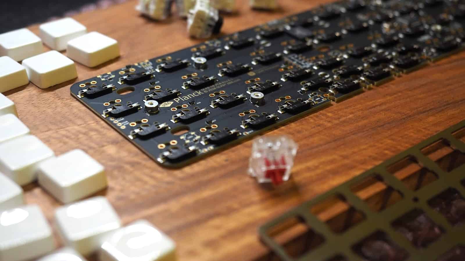
Choosing the Right Microcontroller
The first step in creating a microcontroller PCB is selecting the appropriate microcontroller for your project. There are numerous options available, each with its own features, capabilities, and price points. Some popular microcontroller families include:
- Arduino (ATmega)
- PIC (Microchip)
- STM32 (ST Microelectronics)
- ESP32 (Espressif Systems)
When choosing a microcontroller, consider factors such as:
- Processing power and speed
- Memory (RAM and ROM)
- Input/Output (I/O) pins
- Peripherals (ADC, PWM, UART, SPI, I2C)
- Power consumption
- Development tools and community support
Comparison of Popular Microcontrollers
| Microcontroller | Processing Speed | RAM | Flash Memory | I/O Pins | Power Consumption |
|---|---|---|---|---|---|
| ATmega328P | 16 MHz | 2 KB | 32 KB | 23 | Low |
| PIC18F45K50 | 48 MHz | 2 KB | 32 KB | 35 | Low |
| STM32F103C8T6 | 72 MHz | 20 KB | 64 KB | 37 | Low to Moderate |
| ESP32-WROOM-32 | 240 MHz | 520 KB | 4 MB | 34 | Moderate |
Designing the PCB Schematic
Once you have selected your microcontroller, the next step is to design the PCB schematic. The schematic is a graphical representation of the electrical connections between components on your board. You can use PCB design software such as KiCad, Eagle, or Altium Designer to create your schematic.
Essential Components for a Microcontroller PCB
- Microcontroller
- Power supply (voltage regulator, capacitors)
- Crystal oscillator (if required)
- Reset circuit
- Programming interface (e.g., ICSP, JTAG)
- Decoupling capacitors
- Pull-up/pull-down resistors
- Connectors (headers, terminal blocks)
Schematic Design Tips
- Use a clear and organized layout
- Group related components together
- Minimize the number of crossovers
- Provide proper power decoupling
- Include test points for debugging
PCB Layout and Routing
After completing the schematic, you can proceed to the PCB layout and routing phase. This involves arranging the components on the board and connecting them with traces (copper paths).
PCB Layout Considerations
- Component placement for optimal signal integrity
- Trace width and spacing based on current requirements
- Ground plane for improved noise immunity
- Proper Power distribution
- Minimizing electromagnetic interference (EMI)
- Manufacturability (e.g., minimum trace width, hole sizes)
Routing Tips
- Route critical signals first (e.g., clock, reset)
- Keep traces as short as possible
- Avoid sharp angles (use 45° angles instead)
- Provide adequate clearance between traces
- Use vias sparingly and strategically

PCB Fabrication and Assembly
Once your PCB design is complete, you can send the files (Gerber and drill files) to a PCB manufacturer for fabrication. Many online PCB fabrication services offer affordable and quick turnaround times for prototype quantities.
PCB Fabrication Options
- In-house fabrication (for simple, single-layer boards)
- Online PCB fabrication services (e.g., JLCPCB, PCBWay, OSH Park)
- Local PCB manufacturers
PCB Assembly
After receiving your fabricated PCB, you can proceed with the assembly process. This involves soldering the components onto the board.
- Gather the necessary tools (soldering iron, solder, flux, tweezers)
- Start with the lowest-profile components (e.g., resistors, capacitors)
- Work your way up to taller components (e.g., connectors, headers)
- Pay attention to component orientation (e.g., polarized capacitors, ICs)
- Inspect your solder joints for quality and reliability
Testing and Debugging
With your microcontroller PCB assembled, it’s time to test and debug your board to ensure proper functionality.
Testing Steps
- Verify power supply voltages
- Check for short circuits or open connections
- Test the programming interface
- Upload a simple test program (e.g., blink an LED)
- Verify the functionality of peripherals and I/O pins
Debugging Tips
- Use a multimeter to check continuity and voltages
- Employ an oscilloscope for analyzing signals
- Use serial communication for debugging messages
- Isolate issues by testing individual components or sections
- Consult the microcontroller’s datasheet and application notes
Conclusion
Creating a microcontroller PCB can be a rewarding and educational experience. By following the steps outlined in this guide, you can design, fabricate, and assemble your own custom microcontroller board. Remember to choose the right components, design your schematic carefully, and pay attention to PCB layout and routing best practices. With proper testing and debugging, your microcontroller PCB will be ready to power your next electronic project.
Frequently Asked Questions (FAQ)
-
Q: What software do I need to design a microcontroller PCB?
A: You can use PCB design software such as KiCad (free and open-source), Eagle (free for small boards), or Altium Designer (paid, professional-grade). -
Q: Can I fabricate my own PCB at home?
A: Yes, for simple, single-layer boards, you can use methods like toner transfer or UV exposure to fabricate your own PCBs at home. However, for more complex or multi-layer boards, it’s recommended to use professional PCB fabrication services. -
Q: How much does it cost to fabricate a microcontroller PCB?
A: The cost of PCB fabrication depends on factors such as board size, layer count, quantity, and turnaround time. Online PCB fabrication services often offer prototype quantities (e.g., 5-10 boards) for around $10-50. -
Q: What are some common mistakes to avoid when designing a microcontroller PCB?
A: Common mistakes include improper power decoupling, poor component placement, insufficient trace width for current requirements, and lack of ground planes. Paying attention to best practices and double-checking your design can help avoid these mistakes. -
Q: How do I program my microcontroller PCB?
A: The programming method depends on the specific microcontroller you are using. Common methods include using a USB-to-serial adapter, an In-Circuit Serial Programming (ICSP) interface, or a JTAG interface. Consult your microcontroller’s datasheet and programming guide for specific instructions.


Leave a Reply