Understanding Lead-free Soldering Temperatures
Lead-free soldering has become the standard in the electronics industry since the implementation of the Restriction of Hazardous Substances (RoHS) directive in 2006. This directive restricts the use of lead and other hazardous substances in electronic products. As a result, manufacturers have shifted to lead-free solder alloys, which typically have higher melting points compared to traditional lead-based solders.
The most common lead-free solder alloys used in the industry are:
| Alloy | Composition | Melting Point (°C) |
|---|---|---|
| SAC305 | Sn96.5Ag3.0Cu0.5 | 217-220 |
| SAC387 | Sn95.5Ag3.8Cu0.7 | 217-219 |
| SN100C | Sn99.3Cu0.7 + Ni | 227 |
| SnAg | Sn96.5Ag3.5 | 221 |
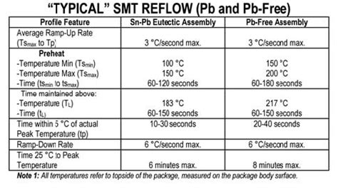
As you can see, the melting points of these lead-free alloys range from 217°C to 227°C, which is higher than the melting point of traditional lead-based solder (183°C for Sn63Pb37).
Factors Affecting PCB Durability During Soldering
Several factors can influence a PCB’s ability to withstand repeated exposure to lead-free soldering temperatures:
-
PCB Material: The base material of the PCB plays a significant role in its thermal stability. Common PCB materials include FR-4, polyimide, and ceramic. FR-4 is the most widely used material and can withstand multiple lead-free soldering cycles without significant degradation.
-
PCB Thickness: Thicker PCBs have better thermal stability and are less prone to warping or deformation during soldering. A standard 1.6mm thick FR-4 PCB can typically withstand more soldering cycles than a thinner board.
-
Copper Thickness: The thickness of the copper traces on the PCB also affects its durability. Thicker copper layers provide better heat dissipation and can withstand more soldering cycles.
-
Soldering Profile: The soldering profile, which defines the temperature curve during the soldering process, can impact the PCB’s longevity. An optimized soldering profile minimizes the time spent at peak temperatures, reducing the thermal stress on the PCB.

Estimating the Number of Safe Soldering Cycles
Based on industry experience and empirical data, a well-designed FR-4 PCB with a thickness of 1.6mm and copper thickness of 1oz (35µm) can typically withstand 3-5 lead-free soldering cycles without significant degradation in its structural integrity or electrical performance.
However, it’s essential to note that this is a general estimate, and the actual number of safe soldering cycles may vary depending on the specific PCB design, components used, and the soldering process employed.
To maximize the number of safe soldering cycles, consider the following best practices:
- Use high-quality PCB materials with good thermal stability, such as FR-4 or polyimide.
- Ensure adequate PCB thickness (1.6mm or thicker) to improve thermal resistance.
- Use appropriate copper thickness for better heat dissipation.
- Optimize the soldering profile to minimize peak temperature duration and thermal stress on the PCB.
- Implement proper handling and storage procedures to prevent physical damage to the PCB between soldering cycles.

Consequences of Excessive Soldering Cycles
Subjecting a PCB to more soldering cycles than it can safely withstand can lead to various issues:
-
Delamination: Repeated thermal stress can cause the layers of the PCB to separate, leading to delamination. This can result in poor electrical connections and reduced mechanical strength.
-
Warping: Excessive heat exposure can cause the PCB to warp or twist, making it difficult to align and solder components accurately.
-
Copper Trace Damage: High temperatures can cause the copper traces on the PCB to oxidize, leading to reduced conductivity and potential open circuits.
-
Component Degradation: Repeated soldering can degrade the quality of the electronic components, affecting their performance and reliability.
To avoid these issues, it’s crucial to monitor the number of soldering cycles a PCB undergoes and to replace the board when it approaches its safe limit.

Frequently Asked Questions (FAQ)
-
Q: Can I use a lead-based solder instead of lead-free solder to reduce thermal stress on the PCB?
A: While lead-based solders have lower melting points, they are restricted by the RoHS directive due to environmental and health concerns. It’s essential to use lead-free solders to comply with regulations and maintain the safety of the end-users. -
Q: How can I tell if a PCB has undergone too many soldering cycles?
A: Visual inspection can reveal signs of degradation, such as warping, discoloration, or delamination. Electrical testing can also help identify any performance issues related to excessive soldering cycles. -
Q: Can I use a lower soldering temperature to increase the number of safe soldering cycles?
A: Lowering the soldering temperature may not be a viable option, as lead-free solders require specific temperature ranges to form reliable joints. Using temperatures below the recommended range can result in poor solder joint quality and reduced reliability. -
Q: Are there any alternative soldering methods that can reduce thermal stress on the PCB?
A: Vapor phase soldering is an alternative method that uses a vapor of a high-temperature liquid to heat the PCB uniformly, reducing thermal stress. However, this method requires specialized equipment and may not be suitable for all applications. -
Q: Can I repair a PCB that has suffered damage due to excessive soldering cycles?
A: In most cases, it’s not recommended to repair a PCB that has undergone excessive soldering cycles, as the damage may be extensive and compromising the board’s overall reliability. It’s often more cost-effective and reliable to replace the damaged PCB with a new one.
Conclusion
Understanding the limitations of PCBs when subjected to lead-free soldering temperatures is crucial for ensuring the reliability and longevity of electronic products. A well-designed FR-4 PCB with appropriate thickness and copper layers can typically withstand 3-5 lead-free soldering cycles without significant degradation.
To maximize the number of safe soldering cycles, manufacturers should use high-quality PCB materials, ensure adequate board thickness, optimize soldering profiles, and implement proper handling and storage procedures.
By monitoring the number of soldering cycles and replacing PCBs when necessary, manufacturers can maintain the quality and reliability of their electronic products while complying with lead-free soldering regulations.


Leave a Reply