Introduction to SEMI-FLEX PCBs
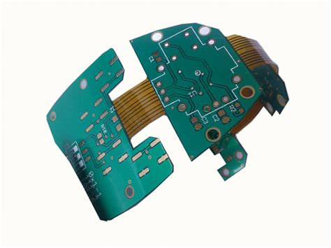
SEMI-FLEX PCBs, also known as semi-flexible printed circuit boards, are a unique type of PCB that combines the features of both rigid and flexible PCBs. These boards consist of a flexible substrate with rigid areas strategically placed to support components and provide structural stability. SEMI-FLEX PCBs offer several advantages over traditional rigid or flexible PCBs, making them an attractive option for various applications in industries such as aerospace, automotive, medical devices, and consumer electronics.
Benefits of SEMI-FLEX PCBs
- Space savings: SEMI-FLEX PCBs allow for more compact designs by eliminating the need for bulky connectors and cables between rigid sections.
- Improved reliability: The flexible substrate provides better shock and vibration resistance compared to rigid PCBs, enhancing the overall reliability of the device.
- Enhanced signal integrity: SEMI-FLEX PCBs minimize signal loss and interference by reducing the number of interconnects required between rigid sections.
- Increased design flexibility: The combination of rigid and flexible areas enables designers to create complex, three-dimensional layouts that would be difficult or impossible with traditional PCBs.
- Cost-effective: SEMI-FLEX PCBs can reduce overall manufacturing costs by simplifying assembly processes and minimizing the number of components required.
SEMI-FLEX PCB Design Considerations
When designing SEMI-FLEX PCBs, several key factors must be taken into account to ensure optimal performance and reliability.
Material Selection
Choosing the right materials for your SEMI-FLEX PCB is crucial for achieving the desired electrical, mechanical, and thermal properties. Some common materials used in SEMI-FLEX PCBs include:
| Material | Description | Advantages |
|---|---|---|
| Polyimide (PI) | A high-performance polymer with excellent thermal stability and mechanical strength. | High flexibility, low dielectric constant, and good chemical resistance. |
| Liquid Crystal Polymer (LCP) | A thermoplastic polymer with unique electrical and mechanical properties. | Low moisture absorption, low coefficient of thermal expansion (CTE), and excellent high-frequency performance. |
| Polyethylene Terephthalate (PET) | A thermoplastic polymer commonly used in flexible electronics. | Good electrical insulation, high mechanical strength, and transparency. |
Bend Radius and Flex Life
The bend radius and flex life are critical parameters in SEMI-FLEX PCB design. The bend radius refers to the minimum radius at which the flexible portion of the board can be bent without causing damage or compromising performance. Flex life represents the number of flex cycles the board can withstand before failure occurs.
To maximize the bend radius and flex life of your SEMI-FLEX PCB:
- Use materials with high flexibility and mechanical strength.
- Minimize the thickness of the flexible substrate.
- Avoid placing components or traces near the bend area.
- Use strain relief features, such as slots or cut-outs, to reduce stress on the flexible portion of the board.
Component Placement and Routing
Proper component placement and routing are essential for optimizing the performance and reliability of SEMI-FLEX PCBs. Some best practices include:
- Place components on the rigid sections of the board whenever possible.
- Avoid placing components near the bend area to minimize stress and strain.
- Use surface-mount components instead of through-hole components to reduce Board Thickness and improve flexibility.
- Route traces perpendicular to the bend direction to minimize stress on the conductors.
- Increase the width of traces in the flexible areas to improve their mechanical strength and current-carrying capacity.

SEMI-FLEX PCB Manufacturing Process
The manufacturing process for SEMI-FLEX PCBs involves several steps that combine the fabrication techniques used for rigid and flexible PCBs.
Substrate Preparation
The first step in SEMI-FLEX PCB manufacturing is preparing the flexible substrate. This typically involves:
- Cleaning the substrate to remove any contaminants.
- Applying a copper layer to one or both sides of the substrate using techniques such as electroless plating or sputtering.
- Laminating the copper-clad substrate with a cover layer to protect the copper during subsequent processing steps.
Circuit Patterning
Once the substrate is prepared, the circuit pattern is created on the copper layer using a photolithographic process:
- A photoresist is applied to the copper layer and exposed to UV light through a photomask containing the desired circuit pattern.
- The exposed photoresist is developed, creating a protective mask over the areas that will form the circuit traces.
- The unmasked copper is etched away using a chemical solution, leaving behind the desired circuit pattern.
Coverlay Application
After the circuit pattern is created, a coverlay is applied to protect the traces and provide electrical insulation:
- The coverlay material, typically a polymer film with an adhesive backing, is cut to size and placed over the circuit pattern.
- The coverlay is laminated to the substrate using heat and pressure, creating a strong bond between the layers.
- Openings are created in the coverlay to expose pads for component mounting and interconnects between layers.
Rigid Area Formation
To create the rigid areas of the SEMI-FLEX PCB, additional layers of rigid material are laminated to the flexible substrate:
- The rigid layers, typically composed of FR-4 or similar materials, are prepared with the necessary circuit patterns and interconnects.
- The rigid layers are aligned with the flexible substrate and laminated using heat and pressure.
- Vias are drilled through the rigid layers to create interconnects between the layers and the flexible substrate.
Component Assembly and Finishing
The final steps in SEMI-FLEX PCB manufacturing involve assembling the components and applying the necessary finishes:
- Components are mounted on the rigid areas of the board using techniques such as surface-mount technology (SMT) or through-hole mounting.
- Solder is applied to the component leads and pads, creating electrical and mechanical connections.
- The assembled board is cleaned and inspected for defects.
- Any required finishes, such as solder mask or surface finishes, are applied to protect the board and improve its durability.

SEMI-FLEX PCB Testing and Quality Control
To ensure the reliability and performance of SEMI-FLEX PCBs, rigorous testing and quality control measures are employed throughout the manufacturing process.
In-Process Inspections
In-process inspections are conducted at various stages of the manufacturing process to identify and correct any defects or issues before they can impact the final product. These inspections may include:
- Visual inspections to check for surface defects, misalignments, or contamination.
- Automated optical inspection (AOI) to detect errors in the circuit pattern or component placement.
- Electrical testing to verify the continuity and isolation of the circuits.
Functional Testing
Functional testing is performed on the completed SEMI-FLEX PCB to ensure that it meets the specified performance requirements. This may involve:
- Connecting the board to a test fixture that simulates its intended operating environment.
- Applying test signals to the board and measuring its response to verify proper functionality.
- Subjecting the board to environmental stress tests, such as temperature cycling or vibration, to assess its durability and reliability.
Reliability Testing
Reliability testing is conducted to evaluate the long-term performance and durability of SEMI-FLEX PCBs under various environmental conditions. Some common reliability tests include:
- Thermal cycling: Exposing the board to alternating high and low temperatures to simulate the effects of thermal stress.
- Bend testing: Repeatedly flexing the board to a specified bend radius to assess its flex life and mechanical stability.
- Humidity testing: Subjecting the board to high humidity levels to evaluate its resistance to moisture-induced failures.
By implementing comprehensive testing and quality control measures, manufacturers can ensure that SEMI-FLEX PCBs meet the highest standards of reliability and performance.

Applications of SEMI-FLEX PCBs
SEMI-FLEX PCBs find applications in a wide range of industries and products where a combination of flexibility, durability, and compact packaging is required.
Aerospace and Defense
In aerospace and defense applications, SEMI-FLEX PCBs are used in:
- Avionics systems
- Satellite communications
- Missile guidance systems
- Unmanned aerial vehicles (UAVs)
The high reliability and resistance to environmental stresses offered by SEMI-FLEX PCBs make them ideal for these demanding applications.
Automotive Electronics
SEMI-FLEX PCBs are increasingly used in automotive electronics, such as:
- Infotainment systems
- Advanced driver assistance systems (ADAS)
- Engine control units (ECUs)
- Instrument clusters
The flexibility and compact packaging of SEMI-FLEX PCBs allow for the integration of complex electronics into the limited space available in modern vehicles.
Medical Devices
SEMI-FLEX PCBs are used in various medical devices, including:
- Wearable health monitors
- Implantable devices
- Surgical instruments
- Diagnostic equipment
The biocompatibility and reliability of SEMI-FLEX PCBs make them suitable for use in medical applications where patient safety is paramount.
Consumer Electronics
SEMI-FLEX PCBs are found in a variety of consumer electronics products, such as:
- Smartphones and tablets
- Wearable devices (e.g., smartwatches, fitness trackers)
- Virtual reality (VR) and augmented reality (AR) headsets
- Gaming controllers
The flexibility and compact form factor of SEMI-FLEX PCBs enable the design of sleek, lightweight, and ergonomic consumer devices.
Future Trends in SEMI-FLEX PCB Technology
As electronic devices continue to become more advanced and compact, the demand for SEMI-FLEX PCBs is expected to grow. Some future trends in SEMI-FLEX PCB technology include:
High-Density Interconnects (HDI)
HDI technology involves the use of fine-pitch traces, micro-vias, and embedded components to achieve higher circuit densities and smaller form factors. The integration of HDI features into SEMI-FLEX PCBs will enable even more compact and complex designs.
Advanced Materials
The development of new materials with improved electrical, thermal, and mechanical properties will enhance the performance and reliability of SEMI-FLEX PCBs. Some promising materials include:
- Carbon nanotubes (CNTs) for high-strength, lightweight substrates
- Graphene for ultra-thin, highly conductive traces
- Biodegradable polymers for environmentally friendly electronics
3D Printing
3D printing technology has the potential to revolutionize SEMI-FLEX PCB manufacturing by enabling the rapid prototyping and production of complex, three-dimensional circuit structures. This could lead to new design possibilities and faster time-to-market for electronic products.
Intelligent SEMI-FLEX PCBs
The integration of sensors, actuators, and other smart components into SEMI-FLEX PCBs will give rise to intelligent, self-monitoring electronics. These smart SEMI-FLEX PCBs could find applications in areas such as:
- Structural health monitoring
- Wearable health devices
- Industrial automation and control systems
As these trends continue to shape the future of SEMI-FLEX PCB technology, designers and manufacturers must stay at the forefront of innovation to meet the ever-evolving demands of the electronics industry.
Frequently Asked Questions (FAQ)
-
What is the difference between a SEMI-FLEX PCB and a rigid-flex PCB?
A SEMI-FLEX PCB has flexible areas that allow for limited bending and flexing, while a rigid-flex PCB consists of alternating rigid and flexible layers that enable more complex, three-dimensional designs. -
Can SEMI-FLEX PCBs be used in high-temperature applications?
Yes, SEMI-FLEX PCBs can be designed to withstand high temperatures by using materials with high thermal stability, such as polyimide (PI) or liquid crystal polymer (LCP). -
How do I choose the right bend radius for my SEMI-FLEX PCB?
The bend radius should be chosen based on the thickness and material properties of the flexible substrate, as well as the desired flex life of the board. Generally, a larger bend radius will result in less stress on the board and a longer flex life. -
Are SEMI-FLEX PCBs more expensive than traditional rigid PCBs?
Yes, SEMI-FLEX PCBs are typically more expensive than rigid PCBs due to the added complexity of the manufacturing process and the use of specialized materials. However, the cost can be justified by the improved performance, reliability, and space savings offered by SEMI-FLEX PCBs. -
Can SEMI-FLEX PCBs be reworked or repaired?
Reworking or repairing SEMI-FLEX PCBs can be more challenging than rigid PCBs due to the presence of flexible areas and the risk of damaging the substrate. However, with proper techniques and equipment, such as specialized soldering tools and low-temperature solder alloys, SEMI-FLEX PCBs can be successfully reworked or repaired.
Conclusion
SEMI-FLEX PCBs offer a unique combination of flexibility, durability, and compact packaging that makes them an attractive option for a wide range of applications in industries such as aerospace, automotive, medical devices, and consumer electronics. By understanding the design considerations, manufacturing processes, and testing requirements associated with SEMI-FLEX PCBs, designers and engineers can create innovative, high-performance electronic products that meet the demands of today’s rapidly evolving market.
As new materials, manufacturing techniques, and design strategies continue to emerge, the potential for SEMI-FLEX PCBs to revolutionize the electronics industry will only continue to grow. By staying at the forefront of these developments and collaborating with experienced SEMI-FLEX PCB manufacturers, companies can position themselves for success in the increasingly competitive and innovative world of electronic product design.


Leave a Reply